Lab 6 PID Speed Control
The goal of this lab was to get experience with PID control.
Prelab : Debugging Data
I created a command START_PID that will be called on the computer side to run PID for 40s. While the robot was running, time, TOF, and PWM data were collected and stored in arrays on the Artemis side. Upon completion, the data was sent back to the computer.Only one of the ToFs on the front was used as I noticed that just one was enough to provide high accuracy.
Position Control Task
I chose to do Task A which involved starting the robot 2-4m from a wall, driving it as fast as possible and stopping it when it is 304mm away from the wall. Distance measurements from the TOF sensors and a P controller was used.
P/I/D Discussion
A simple P controller was used as it is what I started with for simplicity and it worked well. A kp value of 0.04 was used. Given that the max distance away from the wall is 4m, this makes the max speed 160 PWM. This proved to be the value that was a good trade off between the extremley aggresive controller causing overshoot and the very slow controller.
I arrived at this value by first starting with 0.03 as I saw that a lot of students used this value in the 2022 class. I found it to work well but was extremley slow. I increased that value and found that anything above 0.04 was causing too much overshoot.
Range and Sampling Time
I used the long distance mode which allows a range of 3.6m. I was considering adding code to switch to the short mode after a certain distance threshold but the long mode provided sufficient accuracy even close to the wall. I tested the controller starting at various points between 3.5m and 0.1m. The further I started there was slightly more overshoot because of the momentum the car picked up (this was really only seen at Kp = 0.04 not at 0.03). If I started too close, sometimes 40 PWM was not enough of a starting speed to get the car moving (was more of an issue on carpet than smooth floor).
I found the sampling time was about 40ms. I made sure that the distance was only being read and stored whenever new data was ready. Data is also only being sent once the target has been reached which reduces the sampling time. This sampling time is likely what causes any overshoot but it is small enough to still have a successful controller.
PID Function
I wrote the PID function on the Artemis side. The distance measured by the ToF was used to find the error (distance from target) which was then used to determine the PWM value to spin the motors at as well as the direction the robot should move. I also constrained PWM to be between 40 and 255 (range determined in Lab 5).
Plots
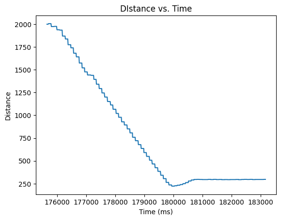
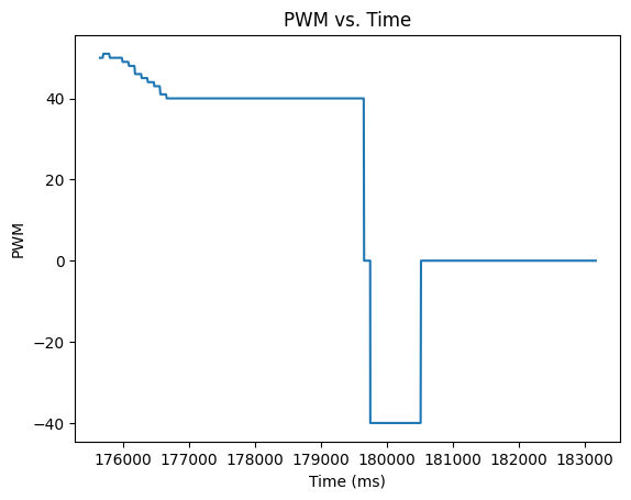
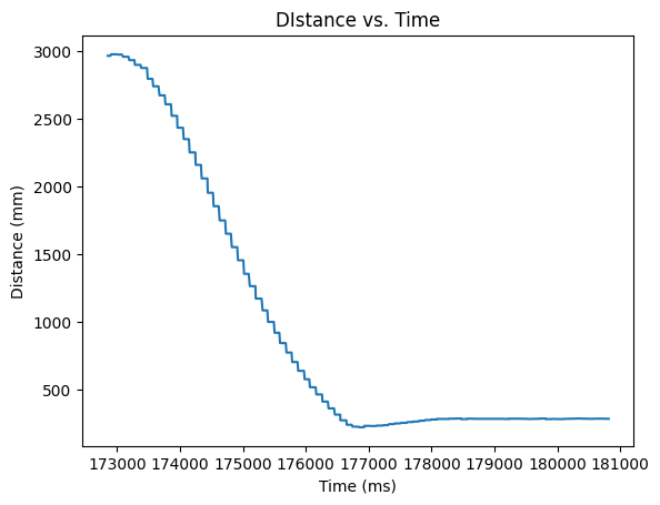
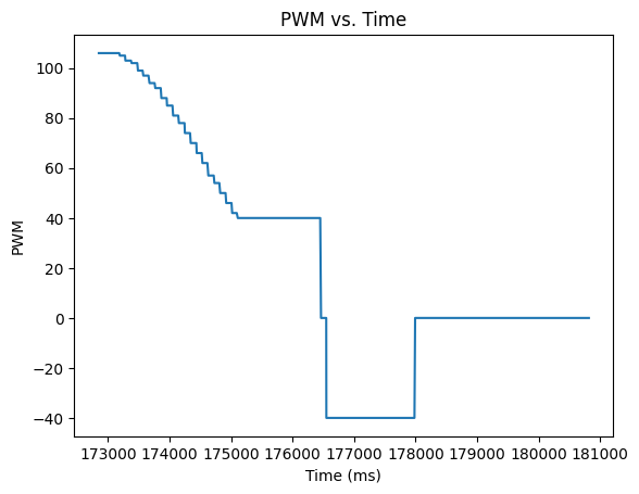
I plotted the distance (mm) from the wall, and signed PWM vs time (millis).
kp = 0.03
kp = 0.04
Videos
Trial 1: Example of very large kp causing overshoot
Trial 2: kp = 0.03 on smooth surface from 2 meters
Trial 3: kp = 0.04 on carpet from 3 meters