Lab 5 Motors and Open Loop Control
The goal of this lab was to setup the motor drivers, install all hardware on the Robot, and demonstrate open loop control.
Prelab
Motor Driver Hookup
I read through the datasheet for the motor driver and understood the pin functions. The motor drivers have two inputs and outputs which will be coupled together in order to deliver enough current to the motor. So, a single dual driver will power a single motor.
Knowing that all the GPIO pins on the Artemis are PWM capable, I decided to use pins A2, A3, 4, and A5 as the inputs to the drivers as they are on the same side as the pin I soldered for the TOF sensor which would save space when installing it in the Robot. I soldered as shown in the diagram using stranded wire and heat shrink. I also twisted cables to reduce EMI. I used the car as a rough reference to determine the optimal length of the wires. I decided to solder all connections so that they were secure as the Robot moved and bumped around.
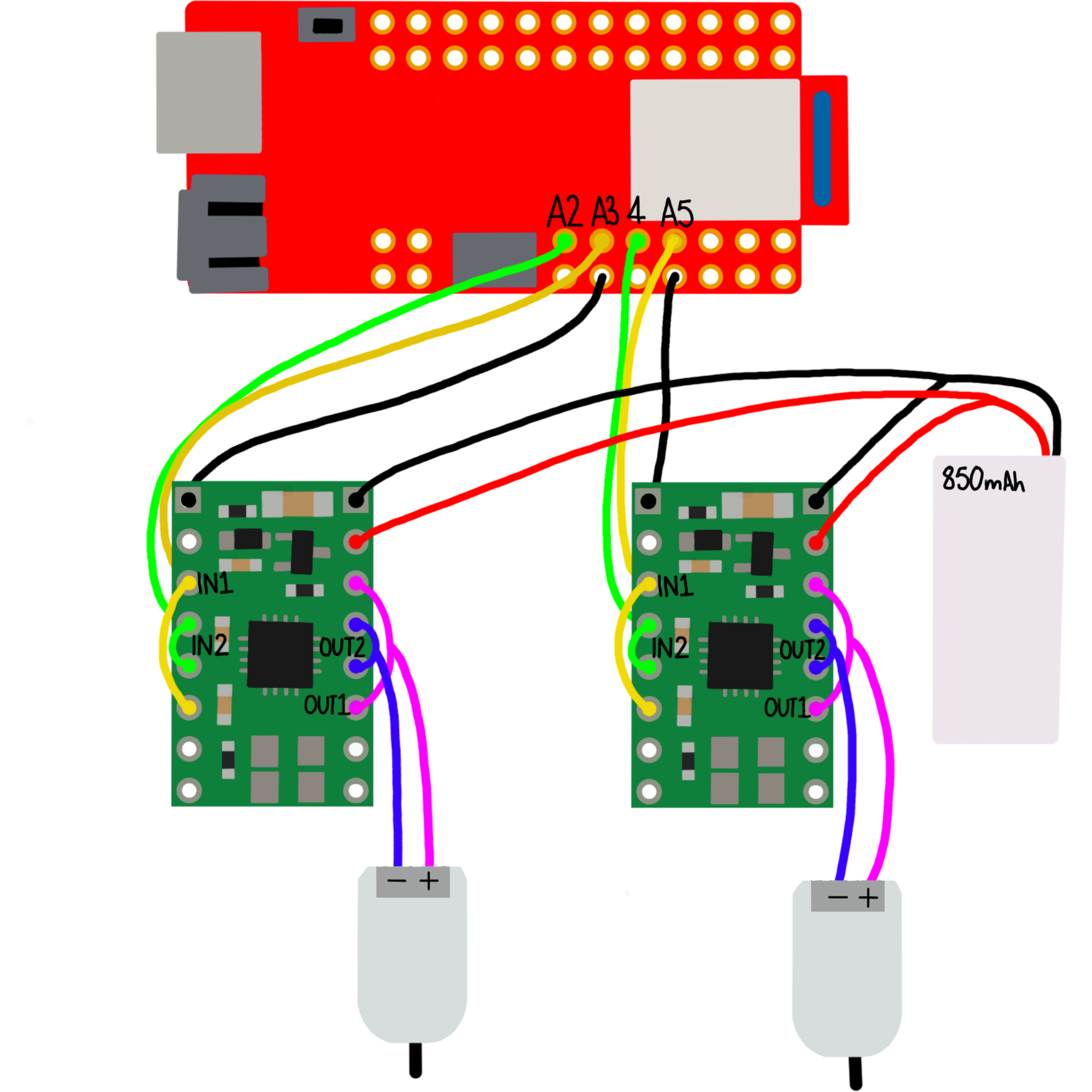
Battery
The motors and the Artemis are powered by different batteries of the same voltage. This serves to reduce noise from the motors affecting the sensors. Additionally, the current draw of the motors is much higher than the Artemis so it is best practice to separate the power paths.
PWM Signal
I then connected the driver to the power supply and oscilloscope as shown in order to monitor the PWM output from the motor driver.
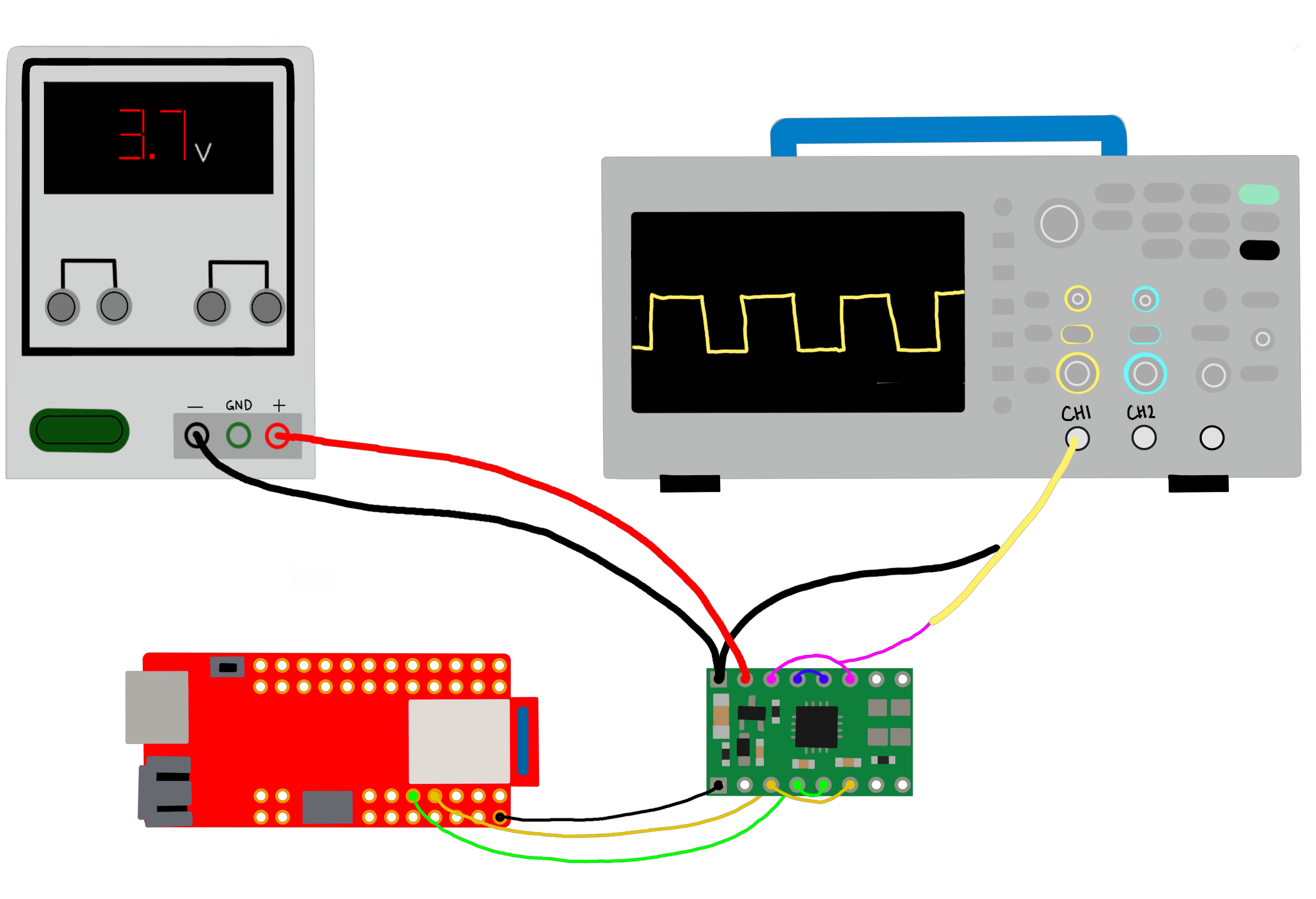
I set the power supply to 3.7V as that is within the drivers input range and is the nominal voltage of the battery we will be using. I set the current limit to 3A as that is slightly higher than the nominal output voltage but under the peak.
I then used an idea from Robby Huang’s (2022) page to test every PWM output from 0-255. I uploaded this code to the Artemis and observed the scope output. I repeated this for both output channels.
Running the Motor
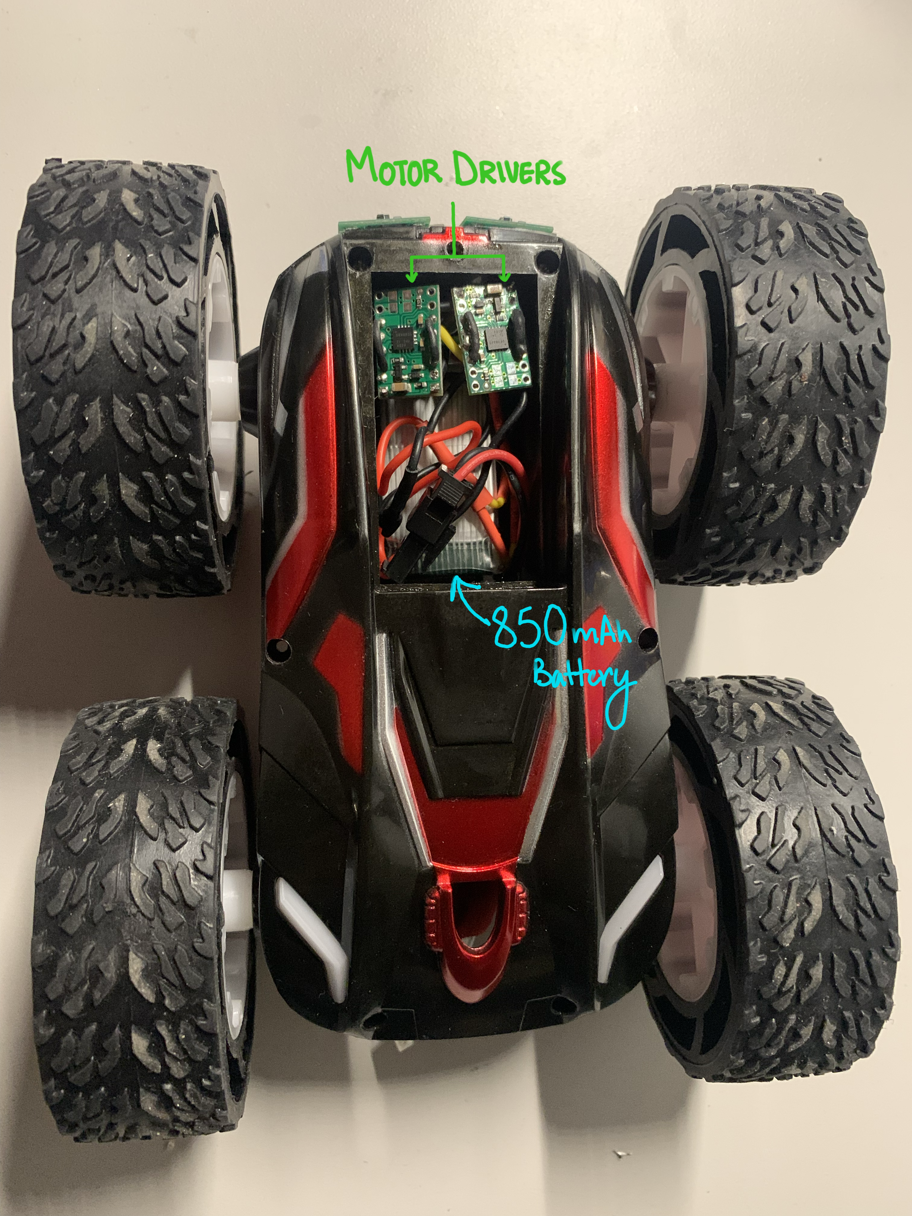
I then took the top shell off the car and got rid of the existing control board. I soldered the drivers output channels to one of the motors. Keeping it powered by the external power supply, I spun the wheels in both directions.
I replaced the power supply with the 850 mAh battery and verified the behavior. I then repeated the above steps with the second motor driver. At this point, all four wheels were spinning and I had a moving Robot.
Install
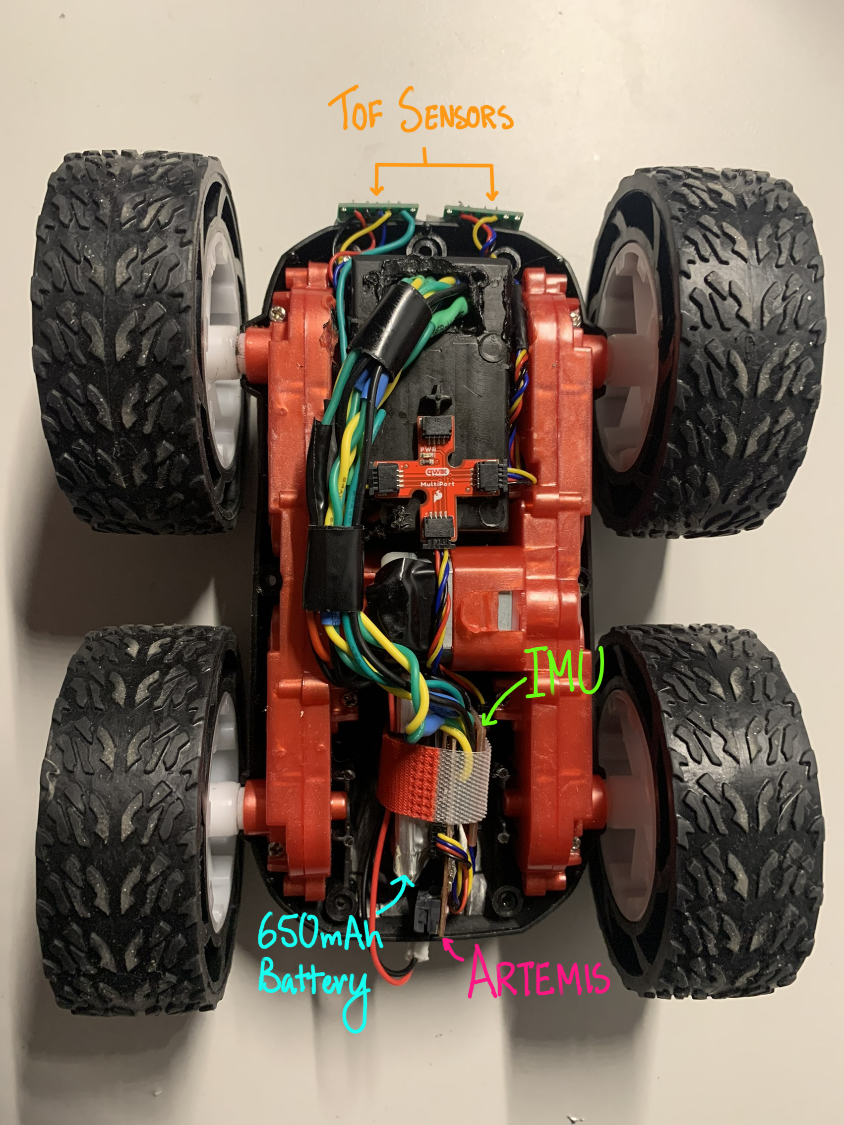
The artemis along with the 650mAh battery only fit in the back cavity so they went there along with the IMU. I velcroed these three together to have a strong but temporary bind to make repairs easier. I had already decided that the TOFs should be in the front. I attached them with some double sided tape. I then cut a hole in the battery compartment and put the motor drivers on the other side as that space was not being utilized much. I twisted all wires, and cut and resoldered any that were too long to reduce EMI.
Lower Limit PWM
If starting from rest, I found that the lowest PWM value for which the Robot moves was 40 on both sides. But, if it is already moving with a higher PWM, the robot is able to move at PWM 30. I tested this by steadily increasing the value from 0 and observing when movement began.
Open Loop Control
My first goal was to see if the two motors were spinning at the same rate by seeing how straight the Robot was going. I set up a tape measure and noticed that the Robot moved in a fairly straight line for 6ft (as shown in the video). I ran it a couple of times and it was not consistently veering off to one particular side, so I decided that a calibration factor is not necessary and the rates of the two motors are similar enough.
I then added some more control in the form of some turns.